3d Vector Component Viewr
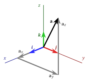
The projections of vector a along the x y and z directions are a x a y and a z respectively.
3d vector component viewr. Shapes can be easily scaled moved mirrored distorted grouped trimmed and cropped. First let s look below at a 3d vector white in a three dimensional coordinate system. This viewer window is run in a separate process spawned by show. The most important use is to generate a vector that can be selected as a toolpath boundary particularly for 3d roughing 3d finishing and also profile cutout toolpaths.
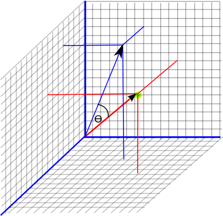
Suppose also that we have a unit vector in the same direction as oa. Graph 3d functions plot surfaces construct solids and much more. Base vectors for a rectangular coordinate system. 3d vectors have x y and z components.
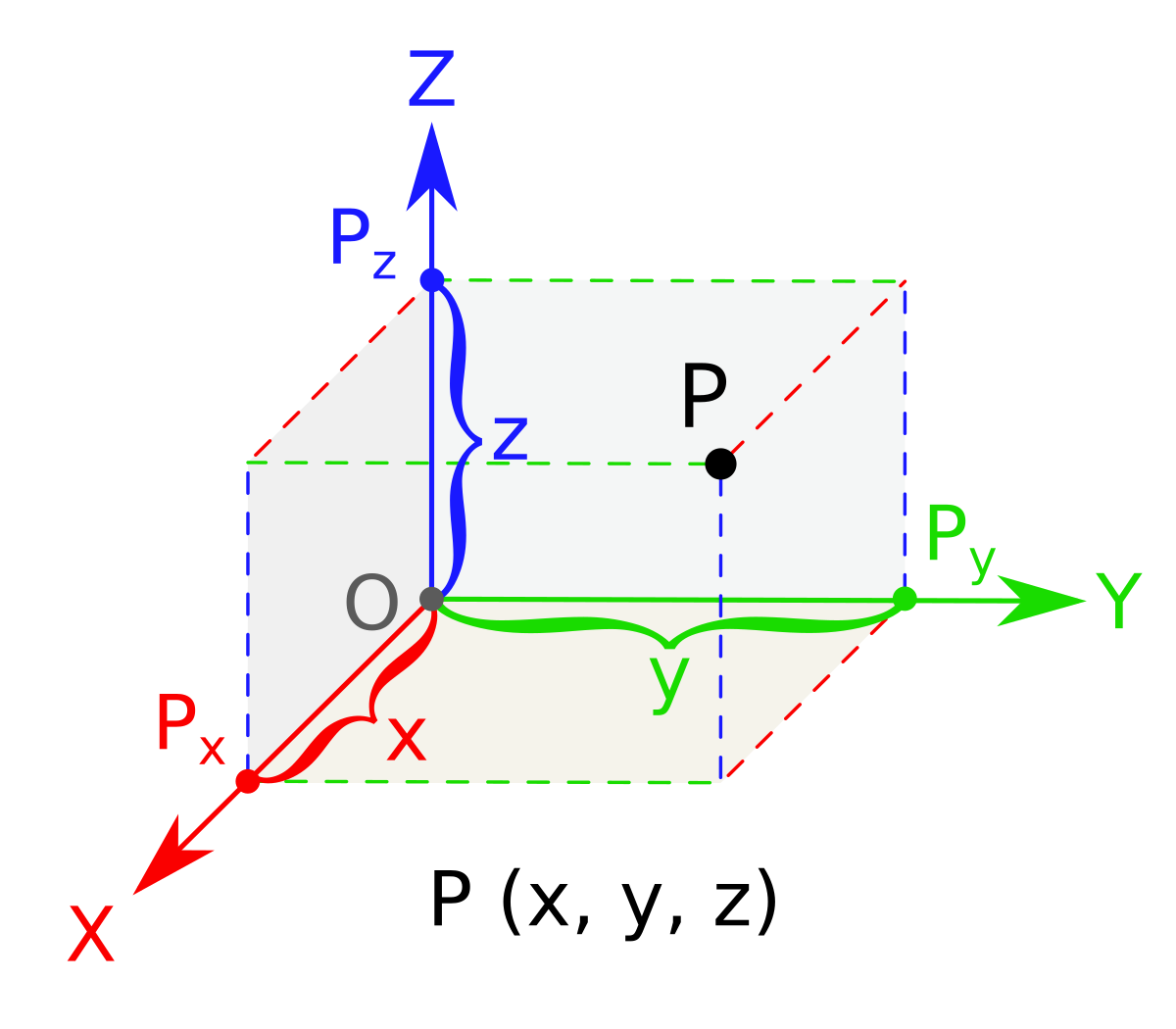
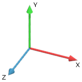
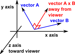
The x component is along the x axis red the y component is along the y axis green the z component is along the z axis blue. Rectangular component of a vector. A set of three mutually orthogonal unit vectors right handed system. Being on a separate process means the rendering of the 3d view does not block the main thread of the calling code and allows the viewer to have its own ui thread with which it can.
This will be imported at the size and position the part was saved in the original file. Maths geometry graph plot vector the demo above allows you to enter up to three vectors in the form x y z. Add vector graphics to your application vectordraw developer framework. Go here for a reminder on unit vectors.
This component opens a window and renders the a 3d view obtained from vector s navigation map. Aspire also allows you to smooth a 3d object or to add draft which creates angled walls on the part good for vacuum forms. Vectordraw developer framework vdf is an easy to program sdk component that every developer need to easily create and manage and print 2d and 3d drawings in his applications. U u 1 i u 2 j u 3 k.
This icon can be used to create a vector around the outermost boundary silhouette of one or more selected components. You can drag the diagram around and zoom in or out by scrolling with the mouse. Suppose we have a vector oa with initial point at the origin and terminal point at a. Shown below are the three components to this three dimensional vector.
Let our unit vector be. Create vector boundary from selected components. Many of the vector editing tools which can be used on 2d data in aspire can also be used to edit 3d components. A vector of unit length.
Clicking the draw button will then display the vectors on the diagram the scale of the diagram will automatically adjust to fit the magnitude of the vectors. A coordinate system represented by base vectors which follow the right hand rule.


